Astatic D104 Schematic Diagram and Information
Site Map
Astatic D104 Schematic Diagram
| Actual Full D104 Schematic With All Technical Information |
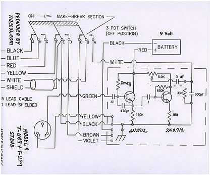
This is the true and total schematic of all power D104 mike stands and if you notice is, not FET transistors but, standard bi-polar,NPN,small signal 2N2712 with data sheet on these, also below. This is an adjustable output from the 5K potentiometer (volume control) center tap and will match any high impedance mike load (HiZ), like 5,000 ohms, plus down to low impedance (lowZ), like 600 ohms. If you want more bass microphone response and using a 600 low Z microphone input, change 5uf electrolytic capacitor on 5K pot (volume control)center tap to say 47uf (or larger) that is at least 50vdc rated (+ lead toward tap). If high impedance (Hi Z) 5 uf capacitor is fine.
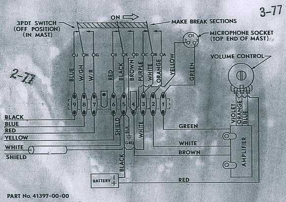
This is the actual wiring diagram that is inside the Astatic powered D104 microphone. (note it matches total schematic above.)
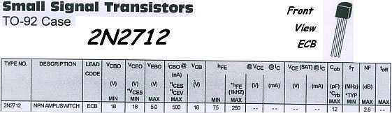
This is a very standard transistor, with ECB pin out, if you use the even more common 2N3904 EBC pin out to replace, just swap the C & B leads then solder in. It is very unlikely one of these transistors will ever fail, since they are under extremely light load. It is most likely 5K adjustment pot or the 5uf capacitor (due to hook up to high voltage on mike lead input) then 2N2712 fail. Using spray cleaner on pot, then adjusting while still wet inside, up and down to clean all contact is very common method. The best scratchy control cleaner ever made is DeOxIT 5(D5) and can be purchased online from an electronic parts dealer. This works for any electronic item, that has adjustable controls, even slide controls (like mixers). 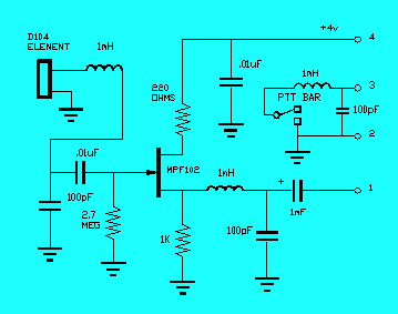
WARNING we have seen the above design on internet to use for a un powered D104. This is a bad design to convert it over to powered, lowZ, Bass response. No one, who really knows amplifier design, uses FET transistors, since they like to oscillate not amplify. BiPolar transistors want to amplify not oscillate, hence much better choice and the reason Astatic "the manufacturer" above used regular transistors in all its powered microphones. You would be much better off to copy the original amplifier design, at the top of this article, that is proven to work correctly. Also you end up with adjustable level plus do not need rf chokes in effort to keep stable (not oscillate all the time "squeal"). You can tell, person who wrote article does not know what he is talking about, since he calls tubes boat anchors and designs for the use of +4 volt supply (Battery??). He needs to learn that when it comes to power and linearity tubes kill transistors every time and still do today. Your microwave oven is tube and only 4 inches square but delivers over a thousand watts of power. The most any transistor can deliver is 120 watts hence it would take 10 transistors with complicated combiner,large heat sink, drivers,pre drivers,oscillator etc.,etc. to accomplish the same task. Several transmitters at radio and TV stations TODAY that are over 1,000 watts use TUBE's. The most valuable and lowest distortion audio amplifiers are tube design (ask any audiophile today). Transistors are of value in low power circuit applications only. I believe it is only a matter of time until broadcast engineers rediscover "Space Modulation" which has been used for aircraft transmitters since 1948. A VOR (Variable Omni Range) ground based transmitter, for example and the most common, has 5 antennas total, not just one. A low power DSB signal to 4 of them in a phased array along with center one getting main high power carrier, can be ran Class E Tube and even more efficient, than hundreds of combined transistor types. Transistors running Class D have a much higher level of distortion and less reliability. Most people have heard of AM, FM & PM but very few SM. These stand for Amplitude Modulation, Frequency Modulation, Phase Modulation, Space Modulation respectfully. I used to think the Russians were behind, for using tubes to control there guided missiles and aircraft (Not Die By Wire), but now realize that tubes work in high radiation, whereas transistors fail and must be radiation hardened to have any hope of working. All of our transistor missiles have radiation hardened transistors and cost 100 times more than normal and still may not work. If hit by a Hydrogen bomb radiation, not the actual blast, hence far away, all transistor products you own will fail, yet tube products will continue to work. Inotherwords Tubes survive EMP (Electro Magnetic Pulse). Just because something is new does not mean it is better, but more likely proven, just cheaper with less quality materials and reliability. Inotherwords (less for less money is not saving but quality for less money is true saving). These microphones interface well with almost any item but, be worry free, since if you purchase a microphone from us, our customer service engineering will help and give the required information/method for any problem in hook up or use. Just email us with make & model of unit you are having a problem hooking up to. Page Design and Images nucow.com copyright It is OK to copy any part of this page to help in a D104 hookup but not to republish for other web site use. This page is dedicated to guests obtaining a free astatic d104 schematic diagram. This d104 skiz from astatic is considered a free d104 schematic diagram. The astatic d-104 is a true collector microphone since made of solid brass and true quality. A d104 skiz sometimes designated d-104 skiz is provided so nucow guests can obtain a free d104 schematic known as an astatic d104 schematic. Let me repeat this again. All page is dedicated to guests obtaining a free astatic D104 schematic diagram. This d104 skiz from astatic is considered a free d104 schematic diagram. Always the astatic d-104 becomes a true collector microphone since made of solid brass and true quality. A d104 skiz sometimes designated d-104 skiz is provided so nucow guests can obtain a free d104 schematic known as an astatic d104 schematic. Complete page is dedicated to guests obtaining a free astatic d104 schematic diagram. A d104 skiz from astatic is considered a free D104 schematic diagram. Astatic D-104 is a true collector microphone since made of solid brass and true quality. D104 skiz sometimes designated D-104 skiz is provided so nucow guests can obtain a free d104 schematic known as an astatic d104 schematic. |